For the OggStreamer frontpanel I needed to come up with a solution to produce light-guides that direct the light from the VU-Meter, Power and On-Air LEDs. The first Idea was to use a 3D Printer and print this light-guides out of transparent PLA. But after trying to imaging how the light-guides would look like, I gave up on this Idea and developed a different process for this. Now I am using the transparent properties of Hot-Glue to act as light-guide and glue the LED-PCB in Place at the same time. The transparent Hot-Glue fills all the space of the CNC-punched holes in the aluminum front-panel. In order to produce a smooth surface I am using a glass plate.
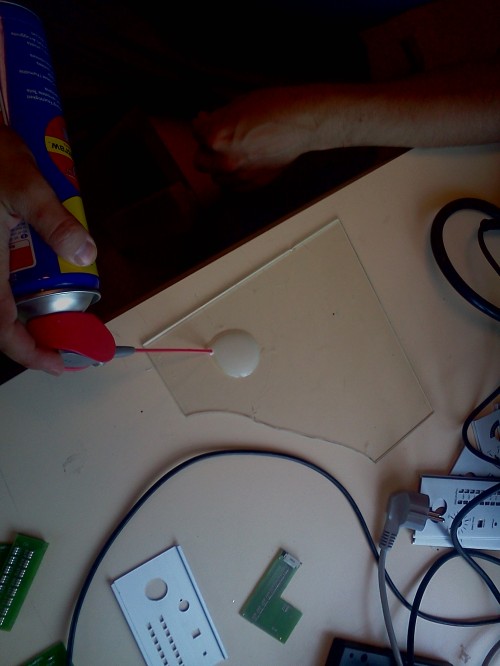
Step 1: You will have to apply a lubricant on the glass plate to form a thin oily film so that the Hot-Glue doesn’t stick to good on the glass – which would make separating the completed assemble from the glass a pain in the a**. (Notice the broken glass plate from our attempts without lubricant!!) WARNING: You are using a glass plate, which can break and have sharp edges. So be careful and don’t apply excessive force – If your assembly got stuck on the glass plate you can use a Hot-Air-Gun to separate it, clean it and repeat the process.
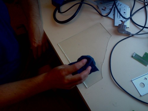
Step 2: Evenly spread the lubricant – don’t wipe it of the plate, but try to produce a tiny but consistent film on the glass plate, without producing droplets.
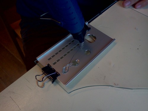
Step 3: Fix the aluminum front-panel with office clips to the glass plate – adjust the office clips in a way so that they will help you aligning the LED-PCB.

Step 4: Wait till your Hot-Glue Gun has reached steady temperature and begin applying the Hot-Glue just over the holes of Power and OnAir LED. Remember to do this and the following steps quickly, because you only have a limited time windows to apply the LED-PCB proper.
Step 5: Do the same for the VU-Meter holes.

Step 6: Once all glue is applied gently push in the LED-PCB – So that the still liquid Hot-Glue is pushed towards the glass plate.
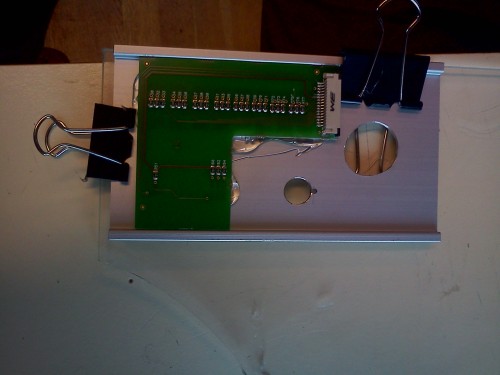
Step 7: The Hot-Glue is still liquid for a few seconds, you can use the time to turn around the glass plate to see if the LED-PCB is properly aligned and if needed adjust its position.

Step 8: Let the assembly cool down – if you are producing more then one unit, you can use this time to prepare the next one.

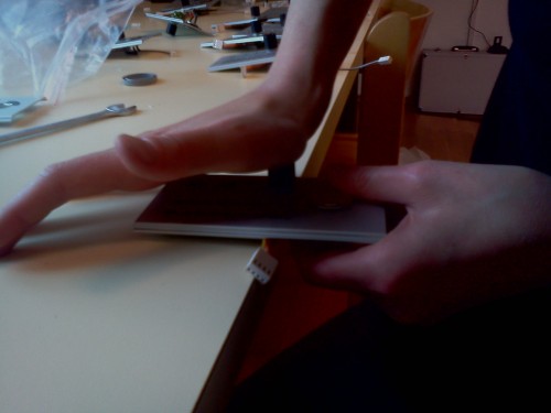
Step 9: Remove the cooled down assembly gently – you shouldn’t need to much force – as the applied lubricant forms a layer between the HotGlue and the glass. In any case be careful – you are handeling a glass plate which has the chance to break – The glass plate you see in the picture broke because we were trying to seperate the assembly from the glass plate using a screw driver.

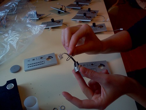
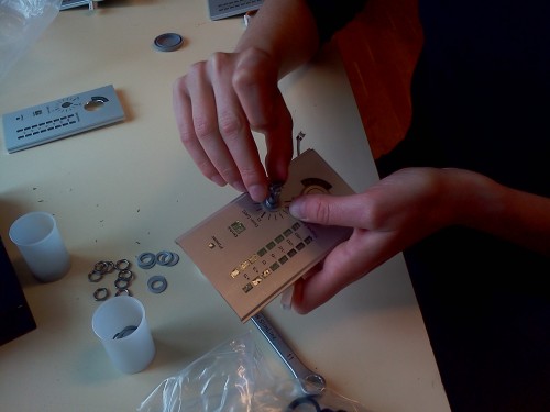
Step 10: Now you can start installing the push button and the potentiometer – We start with the push button first. Take care not to forget about the elastics ring that comes with the push button.
Step 11: Insert the push button from the TOP side.
Step 12: Mount the Pushbutton with plastic Nut – the force of your fingers is enough to mount the plastic nut securly in place

Step 13: Insert the Potentiometer-PCB from the BOTTOM side.
Step 14: Place the washer and the Nut for the Potentiometer from the TOP Side. And gently fix it with the flat wrench.
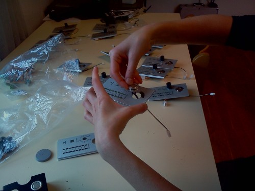
Step 15: Press the prepared Potentiometer Knob on the the Potentiometer – You might need to use a drill (6mm) to prepare the Knob. Only push the Knob with gentle force.
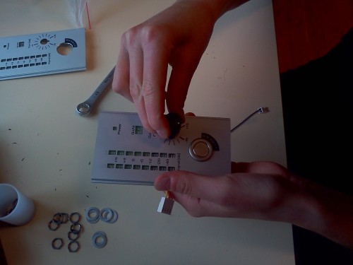
Step 16: Use the corner of a Table (or something similar) to support the Potentiometer from the backside and apply a bit more force so that the Potentiometer Knob is securely mounted to the Potentiometer.
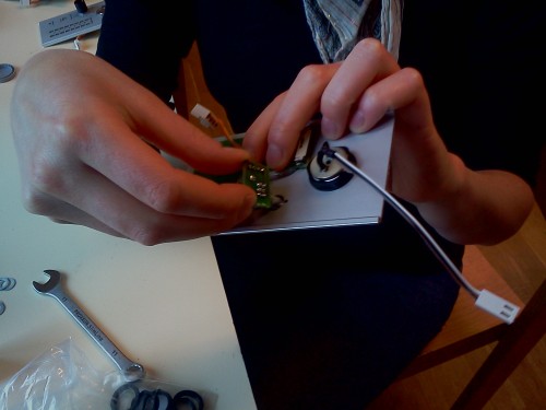
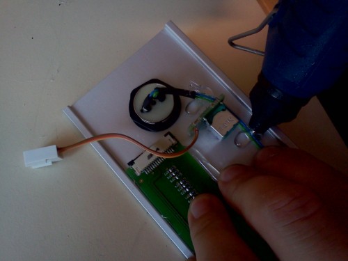
Step 17: Glue the cable of the push button according to the picture. (optional)
The final result:

Although this process works very well – you need to take into account that gluing the PCB in Place makes it a bit harder to repair or replace. You will need to use a Hot Air-Gun to separate the aluminum front-panel from the LED-PCB, further you will need a little patience to remove the glue residue. But it is definitvly doable.